BalanceBot: Simulink-Based Control Deployment on Hardware
🗺 Location: Universite Cote d’Azur / Polytech Nice Sophia, Nice, France
📅 Duration: September 2024 - March 2025
👩🏫 For: Master year 1 R&D project
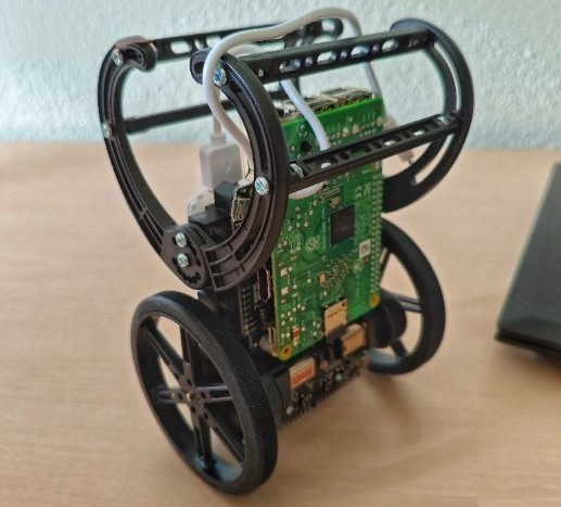
The Sigi wheeled inverted pendulum robot used for the BalanceBot project.
Objective Link to heading
To model, simulate and deploy controllers for a wheeled inverted pendulum robot using MATLAB/Simulink and embedded hardware. The project started with a 1-DOF inverted-pendulum configuration, where the robot’s wheels were constrained and the body pitch was controlled, and later expanded toward a translating 2-DOF balancing robot.
The main goal was to move from analytical modeling and simulation to hardware deployment on the Sigi robot.
System Design Link to heading
Sigi is a wheeled inverted pendulum based on the Pololu Balboa 32U4 balancing robot kit. The control algorithms were developed in MATLAB/Simulink, compiled and run on a Raspberry Pi 3B+, which communicated with the Pololu Balboa32U4 board over I2C.
The control loop included three main parts:
- The physical robot and hardware interface.
- The observer and sensor-processing path.
- The controller implemented in Simulink.
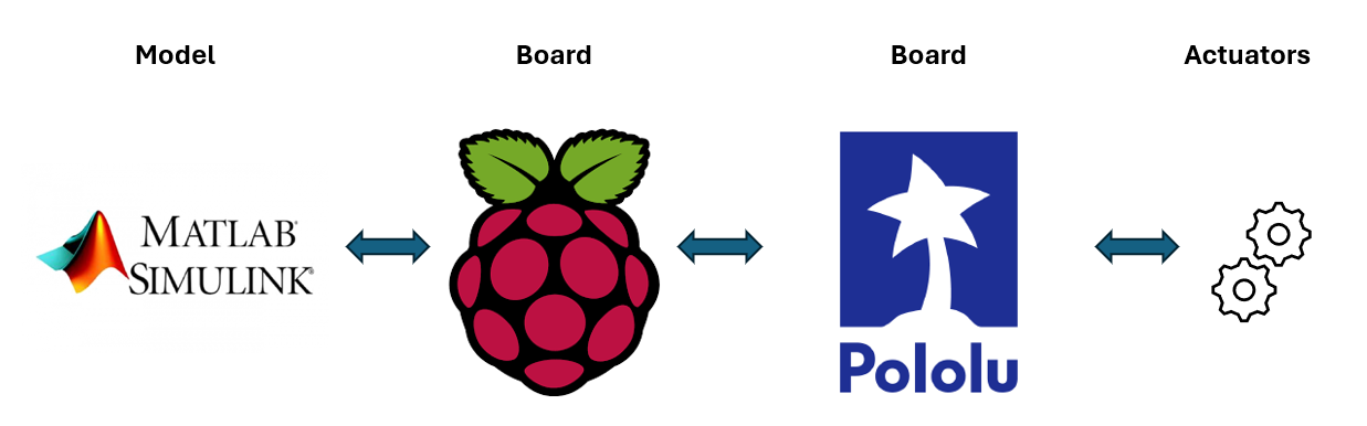
System overview showing Simulink deployment to Raspberry Pi and the Balboa32U4 hardware interface.
Modeling and Control Link to heading
We first estimated robot parameters needed for the model, including gearbox ratio and motor-related constants. Encoder overflow handling was implemented in MATLAB/Simulink to obtain usable wheel-rotation data.
The 1-DOF configuration was modeled as an inverted pendulum with the wheel position constrained. Based on this model, we designed and evaluated:
- PID control using a model-following approach.
- Manual PID tuning inspired by the Ziegler-Nichols method.
- A lead-phase controller with feedback linearization.
The model-following PID produced aggressive gains and did not perform well in simulation. The lead-phase controller worked in simulation but did not transfer well to hardware. The manually tuned PID controller gave the best practical result and was selected for hardware deployment.
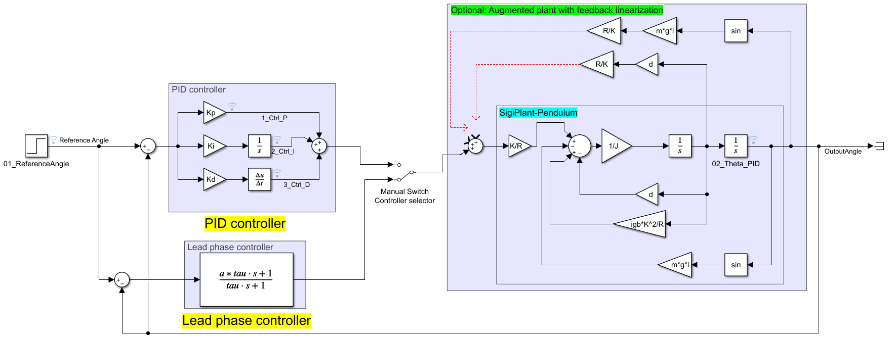
Simulink model used to evaluate the inverted pendulum plant and controllers.
Simulation Results Link to heading
In simulation, the manually tuned PID controller stabilized the 1-DOF inverted pendulum from an initial offset of 10 degrees to near 0 degrees within about 2 seconds.
The project was then extended to a translating 2-DOF model with position, velocity, pitch angle and angular velocity as states. A state-feedback controller and an LQR controller were designed for this model. The simulated controller balanced the robot quickly and returned the linear position toward the origin, but the response also exposed practical constraints such as high angular velocity and actuator saturation.
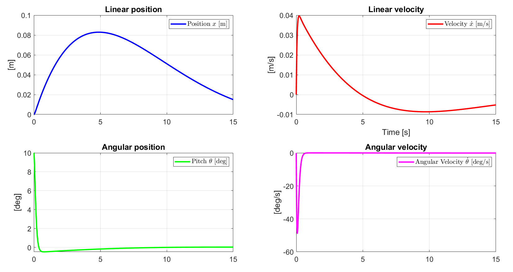
2-DOF translating system simulation result using state feedback/LQR control.
Hardware Implementation Link to heading
The Simulink model was deployed to the Raspberry Pi in external mode, allowing live monitoring and parameter tuning while the controller ran on hardware. For the 1-DOF hardware experiment, the robot’s wheels were pinned so the controller only had to stabilize the body pitch.
The manually tuned PID controller was able to bring the robot body back toward the upright position after disturbances.
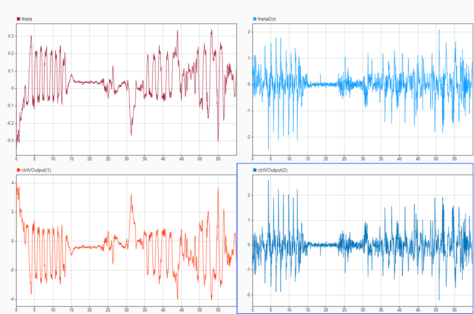
Hardware result from Simulink Data Inspector for the manually tuned PID controller.
Takeaways and Future Work Link to heading
The project demonstrated a complete workflow from physical-system modeling to Simulink simulation and embedded control deployment. It also showed the gap between simulation and hardware: controllers that worked well in simulation did not always transfer to the real robot because of effects such as motor saturation and gearbox backlash.
The 2-DOF translating robot controller worked in simulation but could not be stabilized on hardware within the project timeline. Future work would account for actuator saturation in the controller design, compensate for backlash and then extend the model toward additional degrees of freedom such as yaw control.
Code Link to heading
The code for this project is available here: BalanceBot GitHub repository